
 chinahuijue@gmail.com
 +1 (702) 204-9855
Solar Power for Telecom Towers: How to Choose Grid-Assisted, Off-Grid, or Solar-Diesel Hybrid
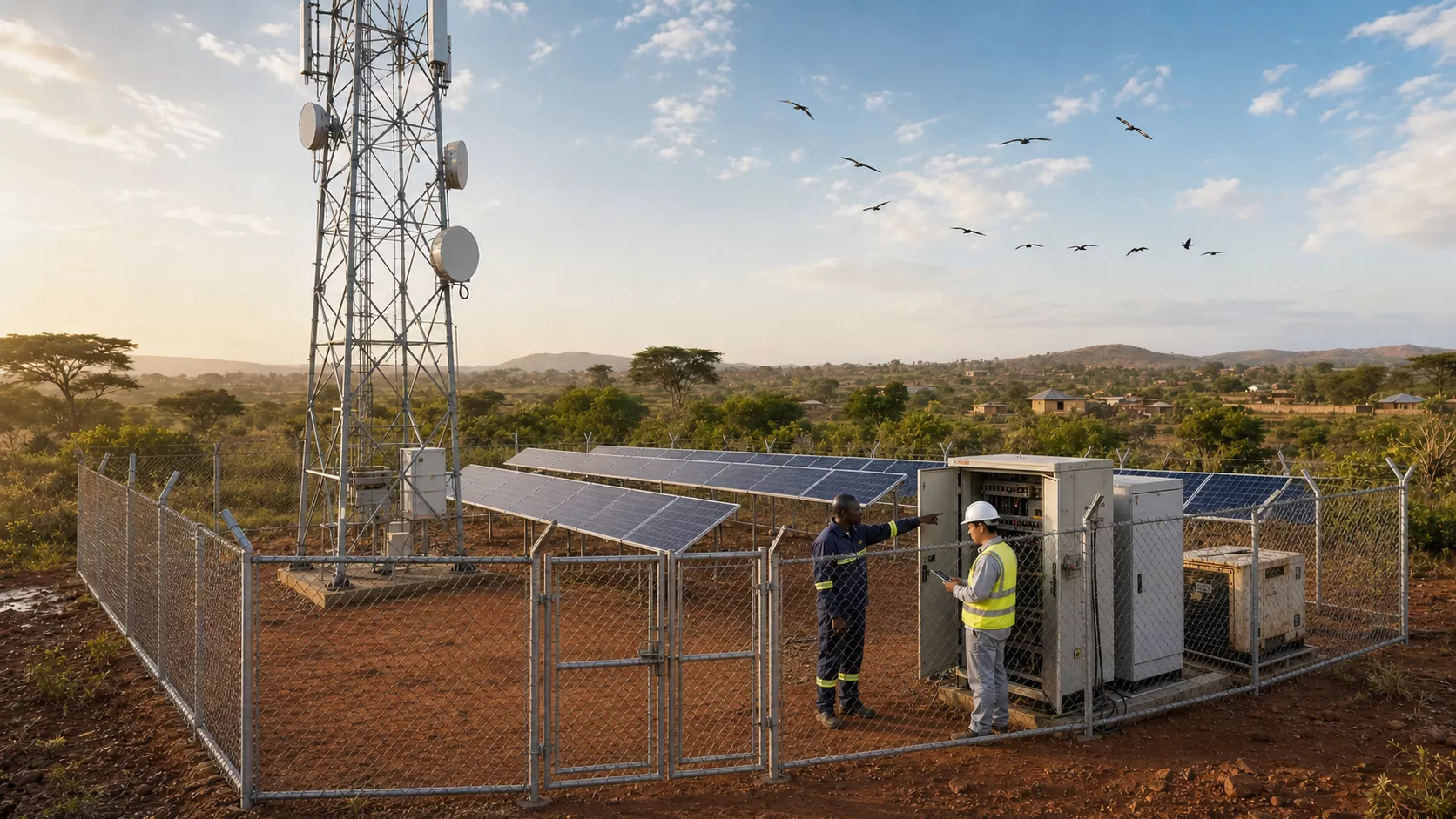
**August 17, 2026 | Engineering Buyer’s Guide **
A telecom tower cannot wait for better weather. Radios, transmission equipment, cooling, security devices, lighting, and network management systems continue to consume power after sunset and during storms.
For weak-grid and off-grid sites, the practical question is not simply whether solar panels can be installed. It is:
**Which combination of solar, battery storage, grid supply, and generator backup can meet the required network availability at an acceptable lifecycle cost?**
The answer usually falls into one of three architectures:
– **Grid-assisted solar** for sites with a usable utility connection
– **Off-grid PV and battery storage** for remote sites with predictable loads and sufficient solar resource
– **Solar-battery-diesel hybrid** for critical sites where extended low-sun periods cannot be allowed to interrupt service
This guide explains how to screen those options, estimate preliminary PV and battery capacity, check recovery performance, and prepare a more useful telecom energy request for proposal.
> **Important:** The calculations below support early engineering and procurement planning. Final ratings, protection, structural design, controls, permits, and installation requirements must be confirmed for the actual site and destination country.
## Quick Decision Guide: Which Architecture Fits the Site?
Choose the operating architecture before selecting equipment. Grid quality, solar resource, fuel logistics, available space, and the cost of an outage will determine which option deserves detailed modelling.
| Site condition | Architecture to evaluate first | Main advantage | Main risk to verify |
|—|—|—|—|
| Reliable grid with useful daytime solar | Grid-assisted solar | Reduces imported electricity and battery cycling requirements | Whether PV and battery remain available during grid outages |
| Weak grid with frequent or long outages | Grid + PV + battery | Reduces outage exposure and generator runtime | Transfer logic, battery reserve, and recovery after an outage |
| Remote site with good solar and a stable load | Off-grid PV + battery | Can eliminate routine fuel delivery | Consecutive low-sun days and slow battery recovery |
| Critical off-grid site | PV + battery + diesel | Solar cuts fuel use while diesel covers exceptional deficits | Poor generator start logic, light loading, and maintenance neglect |
| Temporary or emergency network | Deployable or containerized hybrid | Faster field deployment and factory integration | Transport, anchoring, access, and site-specific shading |
A generator-free design can look attractive because it removes fuel cost and delivery risk. However, enough PV and battery capacity to cover a rare multi-day weather event may cost more than retaining a modest standby generator.
The opposite mistake is also common: an oversized generator runs lightly for long periods, wastes fuel, and suffers avoidable maintenance problems. Do not remove the last backup source until an hourly energy model has passed the design weather cases and the operator has accepted the remaining outage risk.
## Why Telecom Solar Is Different from Ordinary Commercial PV
A grid-connected commercial rooftop normally uses the utility network as an energy buffer. An off-grid telecom site does not have that luxury. When daily solar production remains below daily consumption, battery state of charge falls until the load disconnects or another source starts.
Telecom loads also have a distinctive profile:
– A continuous base load from radios and transmission equipment
– Traffic-related demand changes
– Cooling or heating loads that follow ambient temperature
– Short-duration power peaks
– Smaller auxiliary loads such as obstruction lights, surveillance, access control, and monitoring
– Future load growth from radio or network expansion
Many sites also operate on a nominal **-48 V DC bus**. Where the architecture permits, PV can charge the battery and supply DC loads through an MPPT controller and DC power system without unnecessary DC-to-AC-to-DC conversion. An inverter remains necessary for AC loads, but it should not be added by habit.
Huijue’s Telecom Solar Power Systems solution framework covers PV-replacing-diesel, compact hybrid, and base-station energy scenarios. The final architecture still needs to be based on the site’s measured load and available energy sources.
## Start with Measured Load and Design-Period Solar Data
At minimum, collect:
– Site coordinates
– Hourly or 15-minute load data
– Peak demand
– DC and AC load interfaces
– Grid outage history
– Generator run hours and fuel records
– Cabinet and battery temperature
– Available PV area and shading conditions
– Planned network expansion
– Required autonomy and service availability
The load trace, generator run hours, and delivered-fuel history are especially useful. If they tell different stories, treat the energy baseline as provisional and investigate the difference before sizing equipment.
When interval data is unavailable, build a schedule by subsystem. Do not multiply every nameplate rating by 24 hours. Mark each input as **measured**, **calculated**, or **assumed** so it can be reviewed later.
### Daily Load Energy
The first screening calculation is:
**Daily load energy (kWh/day) = Σ [subsystem power (kW) × operating time (h)]**
Daily energy is used to estimate PV and battery capacity. Peak power must be checked separately because it determines controller, rectifier, inverter, cable, busbar, and protection ratings.
A site can have low average energy consumption while still producing a high short-duration current. Both energy and power matter.
## Preliminary PV Array Calculation
A useful screening equation is:
**PV array (kWp) = Source-side daily energy (kWh/day) ÷ [Design peak-sun hours × PV derating factor]**
Where:
– **Source-side daily energy** includes the downstream losses that the source must supply.
– **Design peak-sun hours** should come from the relevant low-solar design month, not only an annual average.
– **PV derating factor** accounts for module temperature, dirt, mismatch, wiring, MPPT performance, and shading.
Keep the loss boundaries visible. Rectifier and distribution losses belong in the downstream power path. Module temperature and soiling belong on the PV side. If all losses are hidden inside one vague “safety factor,” they may be counted twice or missed entirely.
## Preliminary Battery Calculation
Battery capacity should be based on the energy that must reach the load during the selected autonomy period.
**Nominal battery energy (kWh) = Required autonomy energy ÷ [Allowable DoD × Battery-to-load efficiency × End-of-life retention × Temperature factor]**
Where:
– **Required autonomy energy** is the load energy needed while selected sources are unavailable.
– **Allowable DoD** is the permitted depth of discharge.
– **Battery-to-load efficiency** represents the relevant discharge path.
– **End-of-life retention** is the capacity that must remain at the planned replacement point.
– **Temperature factor** accounts for usable capacity at the design temperature.
Do not apply a derating factor again if the product specification already declares usable energy under the relevant condition.
## Worked Screening Example
Consider a hypothetical remote site with a constant average load of **1.5 kW**.
Its delivered daily load is:
**1.5 kW × 24 h = 36 kWh/day**
Assume:
– Downstream efficiency: 88%
– Planning allowance: 10%
– Design solar resource: 4.0 peak-sun hours
– PV derating factor: 0.78
– Battery autonomy: 12 hours
– Allowable DoD: 80%
– Battery-to-load efficiency: 94%
– End-of-life retention: 80%
| Screening step | Calculation | Result |
|—|—:|—:|
| Daily delivered load | 1.5 × 24 | 36.0 kWh/day |
| Source-side energy target | 36 ÷ 0.88 × 1.10 | 45.0 kWh/day |
| Preliminary PV array | 45 ÷ (4.0 × 0.78) | 14.4 kWp |
| 12-hour autonomy energy | 1.5 × 12 | 18.0 kWh delivered |
| Battery before temperature correction | 18 ÷ (0.80 × 0.94 × 0.80) | 29.9 kWh nominal |
These figures are not a quotation. They represent one transparent set of assumptions. A final design must simulate hourly battery state of charge, consecutive poor-weather days, temperature, load growth, and source outages. It must also round the result to compatible battery modules and verify current at the minimum operating voltage.
## Recovery Time Is as Important as Autonomy
A battery can be large enough to carry the load but paired with too little PV or rectifier capacity to recharge before the next event.
In the example above, restoring **18 kWh** within six hours at 92% charging-path efficiency requires approximately:
**18 kWh ÷ (6 h × 0.92) = 3.26 kW for charging**
The source must also continue supplying the live 1.5 kW telecom load:
**3.26 kW + 1.5 kW = 4.76 kW before additional headroom and losses**
The energy model should therefore report both:
1. The lowest battery state of charge during the design event
2. The time required to restore the selected reserve while the site remains online
For hybrid sites, the same check applies to generator and rectifier capacity. Start and stop thresholds should prevent rapid cycling while allowing the generator to operate within an efficient loading range.
## Component Decisions That Affect Field Reliability
### PV Placement and Structure
Mounting modules on a telecom tower may save ground space, but tower height does not automatically improve solar production. Antennas, steelwork, cables, and vegetation can create complex shading. Added wind area, structural loading, difficult cleaning, and work-at-height access may outweigh the space saving.
Ground-mounted arrays are often easier to orient, inspect, clean, and expand when secure, unshaded land is available.
Check:
– Wind and snow loads
– Corrosion environment
– Soil and foundation conditions
– Cold-temperature string voltage
– Cable routing and lightning protection
– Vegetation growth over the project life
– Safe cleaning and module-replacement access
### Battery and BMS
Lithium iron phosphate batteries are widely evaluated for telecom storage because of their cycle-life and thermal characteristics. Chemistry alone does not guarantee a reliable system.
Review:
– Declared usable energy
– Continuous and peak current
– Low-temperature charging limits
– High-temperature derating
– BMS protection and communication
– Cell or module balancing
– Communication fallback behaviour
– Warranty conditions and replacement responsibilities
Parallel batteries need a validated current-sharing strategy, compatible firmware, and individual branch protection. State-of-charge differences should be controlled before connection to reduce inrush and circulating current.
### DC Power Path and Hybrid Controls
The controller determines when PV serves the load, charges the battery, starts the generator, or uses the grid. Those priorities should follow the operator’s service policy rather than a generic default.
Confirm the complete battery voltage range against the nominal -48 V telecom load, rectifier settings, and low-voltage disconnect. For mixed AC and DC sites, map every conversion stage and its efficiency.
Huijue’s telecom power solution portfolio includes site energy cabinets, hybrid power systems, MPPT controllers, outdoor battery cabinets, and integrated power equipment. Product selection should follow the approved site architecture and interface requirements.
### Cabinet and Environmental Protection
An outdoor enclosure needs more than a headline IP rating. Solar gain, condensation, salt, dust, insects, cable entries, drainage, and internal heat can all affect long-term reliability.
Temperature sensors should represent battery modules and hot components, not only the air near an inlet. Heating, ventilation, and cooling also consume energy and must be included in the load model.
At hot sites, environmental control may protect battery life while increasing daily energy demand. At cold sites, controlled heating may be required before charging is permitted.
### Monitoring That Leads to Action
Useful remote data includes:
– Energy from each source
– Site load
– Battery state of charge
– Cell or module voltage spread
– Battery and cabinet temperature
– Generator starts and run hours
– Fuel level
– Protection and communication events
A dashboard showing 100% state of charge does not prove that the battery can deliver its rated energy. Capacity tests, event history, and trend data provide stronger evidence.
Alarm ownership and response times should be defined before handover. The local controller must retain safe operation if the cloud platform or telecom backhaul becomes unavailable.
## Compare Lifecycle Cost, Not Only Solar Versus Diesel
Sunlight has no fuel invoice, but a telecom solar system still has capital, service, and replacement costs. For diesel comparisons, use the **delivered fuel price at the tower**, not a national pump price.
| Cost category | Frequently missed items |
|—|—|
| Initial deployment | Survey, civil work, fencing, transport, lifting, commissioning, and spares |
| Diesel operation | Delivered fuel cost, losses, theft, generator service, and emergency visits |
| Battery lifecycle | Temperature exposure, throughput, calendar ageing, replacement labour, and transport |
| Solar maintenance | Cleaning, vegetation, damaged modules, loose connections, and structure inspection |
| Network impact | Outage penalties, lost traffic, complaints, and repeated callouts |
| End of life | Battery removal, transport, recycling, and documentation |
Compare at least three cases:
1. The present operating model
2. A solar-hybrid design
3. A higher-renewable design
Test fuel price, battery replacement year, load growth, solar yield, financing cost, and outage consequences. Show the assumptions beside the result. A single payback number hides too much.
## When Solar May Not Be the Best First Investment
Reconsider the architecture when a site has:
– Severe year-round shading
– No secure installation area
– A short remaining lease
– Uncertain or rapid load growth
– An unusually reliable and low-cost grid
– An extreme low-solar season that would require very large reserves
Sometimes efficiency should come first. Repair cooling controls, remove obsolete equipment, correct DC losses, and consolidate loads before expanding supply.
Every continuous **100 W** removed saves:
**0.1 kW × 24 h = 2.4 kWh/day**
That reduction lowers both PV and battery requirements.
## Telecom Solar RFP Checklist
Ask every supplier or integrator:
1. What measured load profile, peak power, and future growth case were used?
2. Which solar dataset, design month, and weather years support the PV size?
3. What losses and design margins are included, and where are their boundaries?
4. How much battery energy reaches the load at beginning and end of life?
5. What happens during consecutive poor-sun days?
6. How long does recovery take while the live load continues?
7. Which loads remain on DC, and where is AC conversion required?
8. How are generator start, stop, loading, and failure handled?
9. What are the battery’s temperature and current limits?
10. How are shading, wind, corrosion, dust, condensation, and theft addressed?
11. Which alarms are available locally and remotely, and who responds?
12. What factory and site acceptance tests demonstrate each operating mode?
13. Which spare parts, firmware support, and field services are available?
14. Who owns battery replacement, transport, and end-of-life handling?
## How Huijue Approaches Telecom Site Energy
Huijue develops integrated telecom site energy systems that coordinate supply, distribution, backup, protection, environmental control, and monitoring around the site’s operating requirements.
Depending on the project, the architecture can include:
– PV generation and MPPT control
– Lithium battery storage
– Nominal -48 V DC power
– Grid and generator inputs
– Environmental control
– Local and remote energy management
The proposal should begin with evidence rather than a predetermined cabinet size. Useful inputs include site coordinates, load profile, autonomy target, voltage window, grid and generator history, climate limits, available solar area, communications protocol, and expected expansion.
From those inputs, the engineering team can compare architectures, define the operating sequence, and identify which assumptions still require field confirmation.
## Frequently Asked Questions
### Can a telecom tower run entirely on solar power?
Yes, when the solar resource, unshaded installation area, battery capacity, and site load are compatible. An hourly model should still test the low-solar season, consecutive poor-weather days, and recovery time. Critical sites may retain a generator or another backup source for rare events.
### How many solar panels does a cell tower need?
There is no dependable panel count based on tower type alone. The answer depends on daily energy demand, module rating, design-month sunlight, temperature, shading, system losses, orientation, and growth margin. Start with kWh per day, not a generic number of panels.
### Does a solar telecom site always need an inverter?
No. Many telecom loads use nominal -48 V DC and can be supplied through a suitable DC architecture. An inverter is required for AC loads. Avoiding unnecessary conversion stages can reduce losses and simplify the power path.
### How much battery autonomy is appropriate?
Autonomy should follow the service target, weather risk, source reliability, and response time. A grid-assisted site may need hours, while a remote off-grid site may require much longer. Longer autonomy also increases cost, footprint, and recharge demand.
### Can solar panels be mounted on the tower?
They can be used in some engineered configurations, but structural loading, wind area, shading, cable routing, RF environment, and maintenance access must be assessed. Ground mounting is often simpler when secure land is available.
## Plan the Architecture Before Selecting the Cabinet
The most useful procurement sequence is:
**Measure the load → classify the site → define the availability target → model the energy balance → verify recovery → select equipment and controls.**
This process helps prevent three common failures:
– A battery that meets an autonomy calculation but cannot supply the required current
– A PV array or rectifier that cannot restore the battery before the next event
– A hybrid system whose source priorities do not match the operator’s service policy
If you are planning a telecom solar or hybrid-power project, send the site coordinates, load profile, outage history, current generator records, available solar area, and autonomy target through Huijue’s project inquiry page. The first useful deliverable should be a transparent energy balance and architecture comparison—not only a product list.
Important Disclaimer
All data regarding cost savings, returns, payback periods, investment costs, etc., mentioned in this article/video are theoretical deductions based on specific assumptions (e.g., annual power consumption of 1 million kWh, electricity tariff of ¥0.8/kWh, photovoltaic utilization hours) – they do not represent actual return commitments nor constitute purchase or investment advice; actual returns may vary significantly due to factors such as sunlight conditions, electricity price fluctuations, equipment and installation costs, and subsidy policies, so please verify the latest market prices independently and consult professionals before making any investment decisions.