
 chinahuijue@gmail.com
 +1 (702) 204-9855
Why Telecom Power Supply Uses -48V: Technical Deep Dive 2025-2026
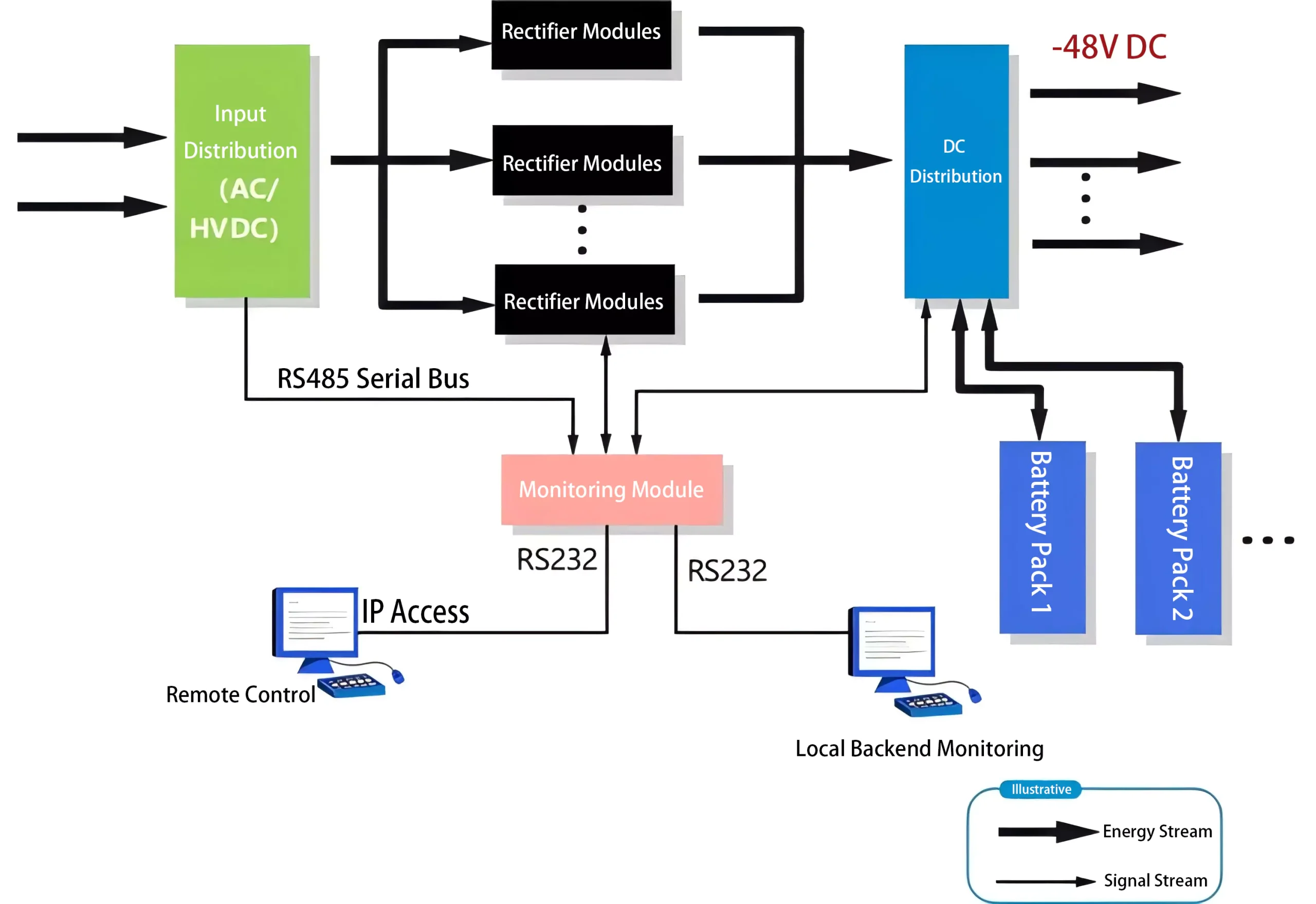
The telecommunications industry has relied on -48V DC power for over a century, yet many engineers and procurement professionals still wonder: why negative 48 volts instead of positive? The answer spans electrochemistry, safety engineering, historical legacy, and international standards. This guide examines every dimension of the -48V telecom power standard — from its origins in early telephone exchanges to its role in modern 5G infrastructure and the emerging HVDC migration.
Quick Answer
| Question | Answer |
|---|---|
| Why -48V and not +48V? | Positive grounding prevents electrochemical corrosion of copper telephone cables in damp environments; copper ions migrate from ground rod to wire, protecting signal cables |
| What is the operating voltage range? | Nominal -48V; operating range -40V to -60V DC; float charge -53.5V to -54.5V; equalize charge -56V to -58V |
| What standard governs it? | ITU-T L.1200 (DC power feeding interface), ETSI EN 300 132-2, ATIS-0600319, NEBS GR-63-CORE |
| Is -48V being replaced? | HVDC (240V-400V) is growing in data centers, but -48V remains dominant for telecom; hybrid systems are emerging |
| Global market size (2025) | $6.8 billion → projected $15.5B by 2035 (CAGR 8.6%); Asia-Pacific >40% share |
| How is -48V generated? | AC input (220V/380V) → rectification → filtering → voltage stabilization → -48V DC output |
| Rectifier efficiency (2025) | Modern switch-mode rectifiers achieve 96-98% efficiency (Tier II/III); 5G sites require ≥97% |
| Which countries use -48V? | Globally adopted; some European legacy systems use -60V; convergence toward -48V standard |
1. Utility Power Classification: The Input Foundation
Before understanding -48V DC output, it is essential to examine what feeds into the system. Telecom power supplies accept utility AC power and convert it through multiple stages to stable DC. The input utility power is classified as follows:
| Parameter | Single-Phase AC | Three-Phase AC |
|---|---|---|
| Voltage | 220V (phase-to-neutral) | 380V (phase-to-phase) |
| Configuration | 1 live wire + 1 neutral | 3 live wires + 1 neutral |
| Frequency | 50 Hz or 60 Hz | 50 Hz or 60 Hz |
| Primary use | Small BTS, indoor DAS, edge nodes | Macro base stations, data centers, MTSO |
| Typical power capacity | Up to ~10 kVA | 10 kVA to several MVA |
| Conversion path | AC → Rectifier → DC bus (-48V) → Load | AC → Rectifier bank → DC bus (-48V) → Load |
The utility power enters the telecom power system through a main distribution panel (MDP), which provides surge protection, isolation transformers, and circuit breakers before the power reaches the rectifier modules. Depending on the site classification — indoor, outdoor, or shelter — the input configuration may vary, but the DC output standard remains -48V.
| Telecom Site Type | Typical Input | Power Range | -48V System Capacity | Battery Backup |
|---|---|---|---|---|
| Outdoor micro/small cell | Single-phase 220V | 0.5-3 kW | 50-300A | 2-8 hours |
| Macro base station (BTS) | Three-phase 380V | 3-15 kW | 300-1000A | 4-8 hours |
| Access node / BSC | Three-phase 380V | 10-30 kW | 600-2000A | 4-8 hours |
| Core switch / MTSO | Three-phase 380V + generator | 30-200 kW | 2000-10000A | 8-24 hours |
| Data center (co-located) | Three-phase 380V + UPS + generator | 100 kW – multiple MW | Custom HVDC or -48V | N+1 or 2N redundant |
2. How -48V Power Is Generated: The Four-Stage Process
The transformation from AC utility to -48V DC follows a precise four-stage process. Modern systems use switch-mode rectifier (SMR) technology, which has largely replaced older linear and ferroresonant designs due to superior efficiency, power density, and controllability.
Stage 1: Utility Input & Protection
AC power (220V or 380V) enters through surge protective devices (SPDs), isolation transformers, and AC distribution units. The input stage includes:
- SPD Class B (Type 1): 40kA surge protection at the main entrance
- SPD Class C (Type 2): 20kA secondary protection at the distribution panel
- AC circuit breakers: Rated at 1.5× the full-load current of the rectifier system
- EMI/RFI filters: Compliant with CISPR 22 / EN 55032 Class A
Stage 2: Rectification
The rectifier converts AC to DC. Modern telecom rectifiers use high-frequency PWM (pulse-width modulation) topology:
| Rectifier Type | Efficiency | Power Density | Power Factor | Status (2025) |
|---|---|---|---|---|
| Linear (legacy) | 40-55% | Low | 0.6-0.7 | Phased out |
| Ferroresonant (legacy) | 70-80% | Medium | 0.7-0.8 | Phased out |
| SCR phase-controlled | 85-88% | Medium | 0.8-0.85 | Legacy sites |
| Switch-mode (SMR) — Standard | 92-95% | High | ≥0.99 | Mainstream |
| Switch-mode (SMR) — High-efficiency | 96-98% | Very High | ≥0.99 | 5G / Green sites |
Stage 3: Filtering
The rectified DC contains ripple and noise that must be reduced before it reaches sensitive telecom equipment. Filtering requirements are defined by ITU-T standards:
| Filtering Parameter | Specification | Standard Reference |
|---|---|---|
| Wideband noise (telephone) | ≤ 2 mV psophometric | ITU-T G.473 |
| Wideband noise (broadband) | ≤ 100 mV p-p (3.4 kHz – 150 kHz) | ETSI EN 300 132-2 |
| Narrowband noise | ≤ 5 mV rms (individual frequency) | ETSI EN 300 132-2 |
| Ripple (peak-to-peak) | ≤ 200 mV p-p at full load | ATIS-0600319 |
| Transient response | Recovery ≤ 200 ms for 25-100% load step | NEBS GR-63-CORE |
Stage 4: Voltage Stabilization
The stabilized output maintains -48V DC within a tight tolerance band. The voltage is regulated using feedback control loops that adjust the PWM duty cycle in real-time:
| Operating Mode | Voltage Range | Typical Set Point | Conditions |
|---|---|---|---|
| Discharge (battery) | -40.5V to -43.0V | — | Battery only, no rectifier |
| Normal operation | -46.0V to -52.5V | -48.0V nominal | Rectifier supplying load |
| Float charging | -53.5V to -54.5V | -53.6V (VRLA) / -54.0V (Li-ion) | Rectifier + battery on bus |
| Equalize charging | -55.0V to -58.0V | -56.0V (VRLA only) | Periodic maintenance charge |
| Low voltage disconnect (LVD) | -43.2V to -44.0V | -43.5V | Protect battery from deep discharge |
| High voltage alarm | -58.0V to -60.0V | -58.5V | Rectifier fault or overcharge |
3. Why -48V and Not +48V? The Core Question
This is the question that defines the entire -48V standard. Three primary factors drove the selection of negative 48V with positive grounding:
3.1 Historical Origins: The Telephone Exchange Era
In the late 1800s and early 1900s, telephone exchanges used electromagnetic relays and carbon microphones that required a central battery supply. The Bell System adopted -48V for several practical reasons:
| Era | Equipment | Voltage Used | Key Driver |
|---|---|---|---|
| 1880s-1920s | Manual switchboards, carbon transmitters | 24V → 48V | Adequate loop length for subscriber lines |
| 1920s-1970s | Step-by-step (SxS) switches, crossbar | -48V standardized | Relay coil current optimization; corrosion prevention |
| 1970s-2000s | Digital switches (5ESS, DMS-100) | -48V | Backward compatibility; semiconductor design optimized for -48V |
| 2000s-present | IP/MPLS, 3G/4G/5G equipment | -48V | Infrastructure inertia; global standardization |
The original choice of 48V (rather than 24V or 60V) was a compromise: high enough to drive signals over several kilometers of copper wire, yet low enough to be safe for technicians handling bare wires. The negative polarity was chosen for corrosion reasons — as explained next.
3.2 Electrochemical Corrosion Prevention: The Decisive Factor
This is the single most important technical reason for -48V (positive grounding). In early telephone systems, cables used cloth-based insulation that absorbed moisture in damp environments. When a voltage potential exists between a copper wire and ground in the presence of moisture, an electrochemical cell forms — essentially a plating process that dissolves metal from one electrode and deposits it on the other.
| Grounding Configuration | Voltage Polarity | Ion Migration Direction | Effect on Copper Wire | Effect on Ground Rod |
|---|---|---|---|---|
| Positive ground (-48V system) | Wire is negative; ground is positive | Cu²⁺ ions: ground rod → wire | Protected — copper deposited on wire | Minimal loss (rod is large mass) |
| Negative ground (+48V system) | Wire is positive; ground is negative | Cu²⁺ ions: wire → ground rod | Corroded — copper stripped from wire | Copper deposited on rod |
| No ground (floating) | No reference | No net migration | No corrosion, but safety risk | No effect |
The physics is straightforward: in a positive-ground system, the copper telephone wire acts as the cathode (negative terminal) of the electrochemical cell. Copper ions in the damp soil are attracted to the cathode and deposit onto the wire, preserving the critical signal-carrying conductor. Meanwhile, the ground rod (anode) loses a small amount of copper — but since it is a large, replaceable piece of copper, this loss is negligible.
With negative grounding (+48V), the wire becomes the anode and is slowly dissolved. Over months or years, the wire thins, resistance increases, and eventually the circuit fails — a catastrophic problem for telephone networks with thousands of miles of buried cable.
3.3 Safety: Human Body Protection
The safe voltage for human contact is generally considered to be ≤36V DC (per IEC 60479-1). At 48V, the system exceeds this threshold, so grounding polarity matters for safety:
| Fault Scenario | -48V (Positive Ground) | +48V (Negative Ground) |
|---|---|---|
| Technician touches positive bus | At ground potential — no shock | +48V above ground — shock risk |
| Technician touches negative bus | -48V below ground — current flows through grounding system, not body | At ground potential — no shock |
| Ground fault on equipment frame | Frame bonded to ground = positive; fault current flows through ground bond | Frame bonded to ground = negative; if wire touches frame, short circuit trips breaker |
| Insulation degradation | Current flows to ground via ground rod — detectable by ground fault detector | Current flows from positive wire to ground — may not be detected |
| Lightning surge | Positive ground acts as discharge path — surge diverted to earth | Negative ground less effective for certain surge types |
In a -48V system, the positive terminal is bonded to the building ground system, which is connected to earth via a ground electrode (typically a copper rod driven into soil or a ring ground). This means the positive bus bar is at earth potential — safe to touch. The negative bus bar sits 48 volts below ground, so touching it while also touching ground would create a current path through the body. However, because the body’s resistance is typically 1,000-100,000 ohms, the resulting current at 48V is 0.48-48 mA — below the 50 mA “let-go” threshold defined in IEC 60479-2.
3.4 Technical Factors: Line Loss and Equipment Design
| Factor | -48V Implication | Quantitative Impact |
|---|---|---|
| Line loss (P = I²R) | Higher current than HVDC, but manageable over short telecom runs | At 48V/100A: 4.8 kW; AWG 2/0 cable @ 30m: ~1.1V drop (2.3%) |
| Relay coil operation | Optimal for 48V DC relays used in telecom cross-connect | Coil resistance ~2000Ω; current ~24mA; power ~1.2W |
| Semiconductor compatibility | Early transistors designed for 48V telecom rails | JEDEC standards for 48V-rated components; e.g., 2N3055 (60V Vceo) |
| Battery cell count | 24 cells × 2.0V (VRLA) = 48V nominal; 15 cells × 3.2V (LiFePO₄) = 48V | Standard 12V/24V/48V battery configurations align |
| DC-DC converter range | Wide input range (36-75V) covers the full -48V operating band | Industry-standard “brick” converters: 48V input (36-75V), 3.3V/5V/12V outputs |
| Loop length (subscriber line) | 48V drives adequate current over ~5 km of 0.4mm copper | Loop resistance ~270Ω/km; 48V/270Ω = 178mA (sufficient for ringing) |
4. -48V vs +48V: Detailed Comparison
| Parameter | -48V (Positive Ground) | +48V (Negative Ground) | Winner |
|---|---|---|---|
| Polarity | Negative terminal is live; positive = ground | Positive terminal is live; negative = ground | — |
| Corrosion protection | Cu ions deposit on wire (cathodic protection) | Cu ions stripped from wire (anodic corrosion) | -48V |
| Shock safety (positive bus) | At ground potential — safe to touch | +48V above ground — shock risk | -48V |
| Shock safety (negative bus) | -48V below ground — limited risk | At ground potential — safe to touch | +48V |
| Ground fault detection | Current flows to ground — easily detected | Current flows from wire — harder to detect | -48V |
| Lightning protection | Positive ground = natural surge path | Less effective for some surge types | -48V |
| Equipment availability | Universal telecom standard; all vendors | Niche; mainly industrial automation | -48V |
| Standards coverage | ITU-T, ETSI, ATIS, NEBS, GB/T | Limited; mostly IEC 60364 (industrial) | -48V |
| Battery configuration | 24×VRLA or 15×LiFePO₄ = 48V | Same cell count, reversed polarity | Tie |
| Cost | Mass-produced — lowest cost per amp | Specialty — higher cost, limited availability | -48V |
| Global adoption | >95% of telecom DC systems worldwide | <5% (some industrial, old telecom) | -48V |
5. International Standards Governing -48V Systems
The -48V standard is not merely a convention — it is codified in multiple international, regional, and national standards:
| Standard | Organization | Scope | Key Requirements |
|---|---|---|---|
| ITU-T L.1200 | ITU-T | DC power feeding interface (up to 400V) | Defines voltage ranges, connector specifications, and compatibility requirements for DC-powered ICT equipment |
| ETSI EN 300 132-2 | ETSI (Europe) | Powered DC interface (-48V) | Nominal -48V; operating -40.5V to -57V; defines noise, transient, and grounding requirements |
| ATIS-0600319 | ATIS (North America) | DC power systems for telecom | Specifies -48V power system architecture, battery requirements, and distribution design |
| NEBS GR-63-CORE | Telcordia (North America) | Network equipment building system | Environmental, safety, and electromagnetic compatibility for central office equipment |
| NEBS GR-1089-CORE | Telcordia (North America) | EMC and electrical safety | Grounding, surge protection, and EMI requirements for -48V systems |
| NEBS GR-3108 | Telcordia (North America) | Outside plant network equipment | Environmental testing for outdoor telecom equipment powered by -48V |
| GB/T 14715 | China (GB) | Telecom power supply equipment | Chinese national standard for -48V rectifiers, distribution, and monitoring |
| YD/T 282 | China (MIIT) | DC power system for telecom | Industry standard specifying -48V system performance and test methods |
| IEC 60950-1 / 62368-1 | IEC (Global) | IT equipment safety | General safety standard covering -48V powered equipment (ES1 limits: ≤60V DC) |
Rectifier Efficiency Standards (2025)
| Efficiency Tier | Minimum Efficiency (50% load) | Minimum Efficiency (100% load) | Typical Application |
|---|---|---|---|
| Tier I (legacy) | ≥90% | ≥88% | Pre-2015 installations |
| Tier II (standard) | ≥94% | ≥92% | Mainstream BTS, access nodes |
| Tier III (high-efficiency) | ≥96% | ≥95% | 5G macro, green sites, data centers |
| Tier IV (ultra-high) | ≥98% | ≥97% | Cutting-edge 5G/6G, AI edge |
China’s GB 20943-2025 (updated from 2017) now requires all new telecom rectifiers to meet Tier III efficiency standards, aligning with global carbon reduction goals. The EU’s Code of Conduct on Data Centre Energy Efficiency similarly recommends Tier III or higher for new DC-powered installations.
6. Global Adoption: Which Countries Use -48V?
While -48V is the global telecom standard, some regional variations exist, primarily from historical legacy:
| Region / Country | Primary DC Voltage | Historical Variations | Current Trend |
|---|---|---|---|
| North America (US, Canada) | -48V | Some -24V in old rural exchanges | Full -48V; HVDC emerging in data centers |
| China | -48V | — | -48V universal; 240V/336V HVDC in large DCs |
| Japan (NTT) | -48V | -48V adopted since 1980s modernization | -48V; some 400V DC for data centers |
| UK & Ireland | -48V (was -50V) | -50V legacy (GPO/BT pre-1980s) | Converged to -48V |
| Germany (Deutsche Telekom) | -48V | -60V legacy in some exchanges | -48V; 380V DC HVDC pilot projects |
| France (Orange) | -48V | -48V since 1970s | -48V standard |
| Nordic countries | -48V | Some -48V/-60V mixed sites | -48V standard |
| India (BSNL, Airtel, Jio) | -48V | — | -48V; massive 5G rollout |
| Southeast Asia | -48V | — | -48V universal |
| Middle East & Africa | -48V | Some -60V legacy (European influence) | -48V for all new deployments |
| Latin America | -48V | — | -48V universal |
| Australia & NZ | -48V | Some -50V legacy | -48V standard |
Key takeaway: Over 95% of global telecom DC power systems operate at -48V. The remaining ~5% are legacy installations (primarily -50V in old UK/BT sites and -60V in some European exchanges) that are gradually being upgraded to -48V during modernization projects.
7. Telecom Power System Market: Data & Trends
The global telecom power systems market reflects the continued dominance of -48V infrastructure, even as HVDC gains ground in high-power applications:
| Market Metric | 2025 Value | 2035 Projection | CAGR |
|---|---|---|---|
| Global market size | $6.8 billion | $15.5 billion | 8.6% |
| Asia-Pacific market | $2.72B (40% share) | $6.82B (44% share) | 9.6% |
| North America market | $1.36B (20% share) | $2.48B (16% share) | 6.2% |
| Europe market | $1.09B (16% share) | $2.17B (14% share) | 7.1% |
| Middle East & Africa | $0.75B (11% share) | $2.02B (13% share) | 10.4% |
| Latin America | $0.88B (13% share) | $2.01B (13% share) | 8.6% |
| Segment | 2025 Share | Growth Driver |
|---|---|---|
| Outdoor telecom power | 67.4% | 5G macro tower deployment, rural coverage |
| Indoor telecom power | 32.6% | Data centers, edge computing, core network |
| On-grid systems | 53.5% | Urban/suburban infrastructure |
| Off-grid/hybrid systems | 46.5% | Rural sites, solar-diesel hybrid, weak grid areas |
| Battery component | 24.0% of system cost | Li-ion replacing VRLA; CAGR 10.6% |
| 10-50 kW systems | Largest power segment | Macro BTS and medium facilities |
Top Global Telecom Power System Manufacturers (2025)
| Rank | Manufacturer | Market Share | Key Products | Region |
|---|---|---|---|---|
| 1 | ZTE | 13.3% | 5G-ready -48V systems, smart power | China/Global |
| 2 | Huawei | ~11% | AI-driven power, fusion power | China/Global |
| 3 | Schneider Electric | ~10% | EcoStruxure, smart energy management | France/Global |
| 4 | Delta Electronics | ~9% | High-efficiency rectifiers, modular systems | Taiwan/Global |
| 5 | Cummins | ~9% | Hybrid generator + DC power solutions | US/Global |
| 6 | Eaton | ~6% | Power distribution, UPS + DC systems | US/Global |
| 7 | Vertiv | ~5% | Edge computing power, thermal management | US/Global |
| 8 | ABB | ~4% | DC power protection, HVDC solutions | Switzerland/Global |
| — | Others | ~32.7% | Regional players, niche solutions | Various |
Top 5 combined: 52.7% market share — indicating a moderately concentrated market with room for specialized integrators and regional manufacturers.
8. The HVDC Migration: Will -48V Be Replaced?
As telecom and data center power demands escalate — driven by 5G, AI, and cloud computing — the limitations of -48V at high power levels become apparent. High Voltage DC (HVDC) systems operating at 240V, 336V, or 400V offer significant advantages for high-density installations:
| Parameter | -48V DC (Traditional) | 240V HVDC | 336V HVDC | 400V HVDC (ITU-T L.1200) |
|---|---|---|---|---|
| Current at 10 kW | 208A | 42A | 30A | 25A |
| Cable cross-section (10 kW, 30m) | AWG 2/0 (67 mm²) | AWG 8 (8.4 mm²) | AWG 10 (5.3 mm²) | AWG 12 (3.3 mm²) |
| Line loss (10 kW, 30m, copper) | ~530W (5.3%) | ~84W (0.8%) | ~48W (0.5%) | ~25W (0.25%) |
| Conversion stages | AC→DC (-48V) → DC/DC (load) | AC→DC (240V) → DC/DC (load) | AC→DC (336V) → DC/DC (load) | AC→DC (400V) → DC/DC (load) |
| System efficiency | 92-96% | 95-97% | 95-97% | 96-98% |
| Safety (touch voltage) | Safe (ES1: ≤60V) | Hazardous (requires isolation) | Hazardous | Hazardous |
| Primary application | Traditional telecom (BTS, access, core) | Data centers, large 5G sites | High-density data centers | Next-gen ICT, hyperscale DC |
| Standard | ETSI EN 300 132-2 | IEC TS 62040-5 | Chinese GB/T | ITU-T L.1200 |
| Market adoption (2025) | >95% of telecom | Growing in China DCs | Niche (Chinese DCs) | Emerging standard |
HVDC Adoption Timeline
| Phase | Period | -48V Role | HVDC Role |
|---|---|---|---|
| Phase 1: Coexistence | 2020-2028 | Dominant; all traditional telecom | Niche; data center pilots |
| Phase 2: Hybrid systems | 2028-2035 | Legacy + low-power loads | New high-density 5G/6G, AI edge |
| Phase 3: Convergence | 2035+ | Phased out in new large-scale deployments | Dominant for new builds >10 kW |
9. System Architecture & Design Best Practices
9.1 Complete -48V Power System Architecture
| Subsystem | Components | Function | Design Considerations |
|---|---|---|---|
| AC input | SPD, AC breaker, isolation transformer | Surge protection, isolation, switching | N+1 redundancy; auto-transfer switch (ATS) for dual feed |
| Rectifier bay | SMR modules (48V/50A typical), controller | AC→DC conversion; N+1 redundancy | Hot-swappable; CAN/SNMP monitoring; ≥96% efficiency |
| Battery bank | VRLA or Li-ion batteries; 24 cells (VRLA) or 15 cells (LiFePO₄) | Backup power; ride-through during outages | 4-8 hours typical; temperature-compensated charging |
| DC distribution | DC breakers, fuses, bus bars, LVD | Power distribution to loads; protection | Per-circuit protection; load-shedding via LVD at -43.5V |
| Monitoring & control | SMU (system monitoring unit), sensors, SNMP agent | Real-time monitoring; alarms; remote management | SNMP v3, Modbus TCP; proactive alarm escalation |
| Grounding | Ground bar, bonding conductors, ground electrode | Safety, surge dissipation, signal reference | Single-point ground; ≤5Ω electrode resistance |
| Environmental | HVAC, DC fans, smoke/temperature sensors | Thermal management; fire safety | Operating temp -5°C to +40°C (indoor); -40°C to +65°C (outdoor) |
9.2 Battery Technology Selection
| Battery Type | Nominal Voltage | Cycle Life | Operating Temp | Cost ($/kWh) | 2025 Status |
|---|---|---|---|---|---|
| VRLA (AGM) | 2.0V/cell × 24 = 48V | 300-500 cycles | -20°C to +50°C | $150-250 | Legacy standard |
| VRLA (Gel) | 2.0V/cell × 24 = 48V | 500-800 cycles | -20°C to +50°C | $200-300 | Common in outdoor |
| LiFePO₄ (LFP) | 3.2V/cell × 15 = 48V | 2,000-6,000 cycles | -20°C to +60°C | $300-450 | Rapidly growing |
| NMC (Li-ion) | 3.7V/cell × 13 = 48.1V | 1,000-3,000 cycles | -10°C to +60°C | $350-500 | Some 5G sites |
| Ni-Cd | 1.2V/cell × 40 = 48V | 1,500-3,000 cycles | -40°C to +70°C | $500-800 | Extreme environments |
9.3 Controller & Inverter Selection
| Component | Type | Key Spec | Selection Criteria |
|---|---|---|---|
| Solar charge controller | MPPT (recommended) | Efficiency ≥98%; Vmp tracking range 30-150V | For solar-hybrid sites; matches PV array Vmp to battery voltage |
| Solar charge controller | PWM (legacy) | Efficiency 70-85%; fixed voltage | Low-cost small systems; less optimal energy harvest |
| DC-AC inverter (off-grid) | Pure sine wave | THD ≤3%; efficiency ≥92% | For AC loads in off-grid telecom sites; sized 1.5× peak load |
| DC-AC inverter (hybrid) | Bidirectional | Grid-tie + backup; transfer time ≤4 ms | For grid-tied sites with battery backup; UL 1741 compliant |
| DC/DC converter | Buck/boost module | Input 36-75V; output 12V/24V; efficiency ≥95% | Steps down -48V to lower DC voltages for auxiliary equipment |
9.4 Electrical Wiring & Protection
| Protection Device | Function | Typical Rating | Standard |
|---|---|---|---|
| DC circuit breaker | Overcurrent protection; manual disconnect | 1.5× full-load current; 48V/60V DC rated | IEC 60947-2; UL 489B |
| DC fuse | Fast-acting overcurrent protection | 125-200% of conductor ampacity | IEC 60269-2; UL 248-13 |
| SPD (Type 1+2) | Lightning and surge protection | 40kA Imax; 20kA In | IEC 61643-1; UL 1449 |
| LVD (Low Voltage Disconnect) | Protects battery from deep discharge | Disconnects at -43.5V; reconnects at -51.0V | ATIS-0600319 |
| Ground fault detector | Detects insulation degradation | Alarm at 10-100 kΩ insulation resistance | IEC 61557-8 |
| Temperature sensor | Battery temperature compensation | -3 mV/°C/cell (VRLA); -4 mV/°C/cell (Li-ion) | Manufacturer specified |
9.5 Monitoring System Design
| Monitoring Layer | Parameters | Protocol | Alarm Priority |
|---|---|---|---|
| Rectifier level | Output voltage, current, temperature, efficiency, fault codes | CAN bus; RS-485 (Modbus) | Critical (immediate) |
| Battery level | Cell voltage, temperature, SOC, SOH, internal resistance | SMBus; CAN; analog (4-20mA) | Major (≤5 min) |
| Distribution level | Per-circuit current, breaker status, fuse integrity | Modbus TCP; SNMP v3 | Major (≤5 min) |
| Environmental | Temperature, humidity, smoke, door open, water leak | Dry contact; SNMP; Modbus | Minor (≤15 min) to Critical |
| System level (NOC) | Overall site health, power consumption, efficiency (kWh) | SNMP v3; NetFlow; REST API | Aggregated reporting |
10. -48V System Sizing & Cost Reference
| Site Type | Load (kW) | Rectifier Capacity | Battery Bank | Backup Hours | Est. Cost (USD) |
|---|---|---|---|---|---|
| Outdoor micro/small cell | 0.5-1 | 48V/30A (1.4 kW) ×2 | 48V/100Ah Li-ion | 4-6 | $3,000-6,000 |
| Small BTS (rural) | 2-3 | 48V/50A (2.4 kW) ×2 | 48V/200Ah VRLA | 4-8 | $6,000-12,000 |
| Macro BTS (urban) | 5-8 | 48V/100A (4.8 kW) ×3 | 48V/500Ah VRLA/Li-ion | 4-8 | $15,000-30,000 |
| Access node / hub | 10-15 | 48V/100A ×4-5 | 48V/1000Ah Li-ion | 6-8 | $30,000-60,000 |
| Core switch site | 30-50 | 48V/200A ×4-6 | 48V/2000Ah ×2 strings | 8-12 | $80,000-200,000 |
| Data center (per rack) | 5-15 | 48V/300A per rack | 48V/300Ah per rack | 5-15 min (UPS) | $10,000-25,000/rack |
11. Future Outlook: -48V in the 5G/6G Era
| Trend | Impact on -48V | Timeline | Key Data |
|---|---|---|---|
| 5G macro deployment | Strengthens -48V demand | 2024-2030 | 7M+ 5G sites globally; 3-5× power per site vs 4G |
| 5G small cells | New -48V market | 2025-2032 | ~25M small cells projected by 2030 |
| Edge data centers | Mixed (-48V + HVDC) | 2025-2035 | Edge DC market $245B by 2030; -48V for low-power racks |
| AI inference edge | HVDC preferred for high-power | 2026-2035 | AI rack power 40-100 kW; HVDC needed at this scale |
| Solar-hybrid telecom | -48V with solar PV + battery | Ongoing | Off-grid/hybrid: 46.5% of market; solar reduces OPEX 30-60% |
| Li-ion battery adoption | Replaces VRLA in -48V systems | 2024-2030 | Li-ion CAGR 10.6%; 10× cycle life vs VRLA |
| 6G early research | Likely -48V + HVDC hybrid | 2030+ | 6G power density targets 10× 5G; standards TBD |
12. Decision Framework: When to Use -48V vs Alternatives
| Application | Recommended Architecture | Rationale |
|---|---|---|
| Traditional BTS / access node | -48V DC (N+1 rectifier + battery) | Industry standard; universal equipment compatibility; proven reliability |
| Outdoor 5G small cell | -48V DC (compact, 1-3 kW) | Low power; small footprint; outdoor-rated enclosures widely available |
| Rural off-grid telecom | -48V DC + solar PV + Li-ion battery | Solar charge controllers standard at 48V; MPPT optimized for 48V battery |
| Urban data center (low-power racks) | -48V DC (rack-level) | Open Compute Project (OCP) 48V rack architecture; safe, efficient |
| Hyperscale data center (high-power) | HVDC (240V-400V) | Lower line losses at 50+ kW/rack; fewer copper conductors; higher efficiency |
| AI training cluster (100+ kW/rack) | HVDC (400V) or 800V DC | Extreme power density; -48V impractical at this scale |
| Hybrid telecom + edge computing | -48V + DC/DC to HVDC | Preserves -48V telecom legacy; adds HVDC for new high-power loads |
FAQ
1. Why is -48V used in telecom power supply instead of +48V?
-48V (positive grounding) is used primarily to prevent electrochemical corrosion of copper telephone cables. In damp environments, positive grounding causes copper ions to migrate from the ground rod to the cable, protecting the signal-carrying wire. It also reduces shock risk during ground faults since current flows through the grounding resistor rather than the human body.
2. What voltage range is acceptable for a -48V telecom system?
A -48V telecom system typically operates in the range of -40V to -60V DC. The nominal voltage is -48V, but during float charging the voltage may rise to -53.5V to -54.5V, and during equalize charging it can reach -56V to -58V. ITU-T L.1200 defines the acceptable operating window for DC power feeding interfaces.
3. Is -48V being replaced by HVDC in telecom?
While HVDC systems (240V-400V) are gaining traction in data centers and high-power 5G installations due to lower line losses, -48V remains the dominant standard for traditional telecom infrastructure. The migration is gradual, with hybrid systems combining -48V for legacy equipment and HVDC for new high-density loads becoming common in modern facilities.
4. What standards govern -48V telecom power systems?
Key standards include ITU-T L.1200 (DC power feeding interface up to 400V), ATIS-0600319 (DC power systems), ETSI EN 300 132-2 (powered DC interface), and Telcordia NEBS GR-63-CORE and GR-1089-CORE for network equipment safety and electromagnetic compatibility in North America.
5. How does a -48V power system generate DC from AC utility?
The process involves four stages: (1) AC utility input (220V or 380V), (2) rectification converting AC to DC using diode bridges, (3) filtering to remove ripple and noise, and (4) voltage stabilization to maintain -48V output. Modern systems use high-frequency switch-mode rectifiers achieving 96%+ efficiency.
6. What is the global telecom power system market size?
The global telecom power systems market was valued at approximately $6.8 billion in 2025 and is projected to reach $15.5 billion by 2035, growing at a CAGR of 8.6%. Asia-Pacific holds over 40% of the market, driven by large-scale 5G deployment in China and India.
7. Why is the positive terminal grounded in -48V systems?
Positive grounding means the positive terminal is connected to earth, making it the highest potential in the system. This configuration prevents electrochemical corrosion: in damp conditions, copper ions migrate from the larger ground rod to the telephone wire, protecting the critical signal cable rather than corroding it.
8. What is the difference between -48V and -60V telecom systems?
Some European countries historically used -60V systems. The higher voltage reduces current for the same power, lowering line losses over long distances. However, -48V became the global standard due to ITU recommendations and equipment interoperability. Most modern systems worldwide have converged on -48V, though some legacy -60V installations remain.
Looking for Reliable Telecom Power Solutions?
Huijue Group manufactures -48V DC telecom power systems, outdoor battery cabinets, and integrated solar-hybrid solutions for communication base stations worldwide. Our systems are ITU-T compliant, NEBS-ready, and deployed across Asia, Africa, the Middle East, and Europe.
Published: July 28, 2025 | Author: Huijue Group Technical Team | Last updated: July 2025